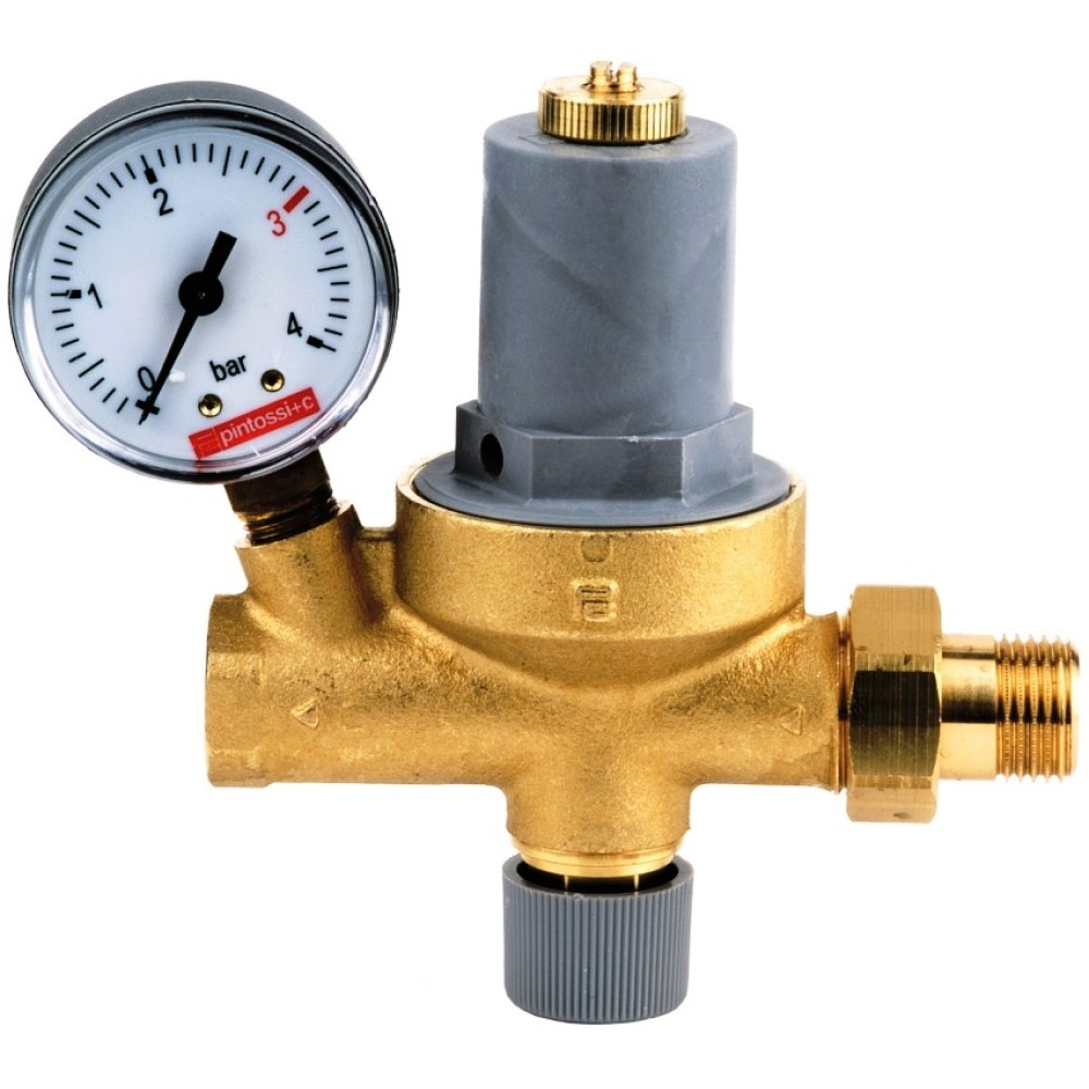
Automatic Filling Valve - with Gauge
£49.74
Ex VAT: £41.45
- Automatically top up system pressure
- Complete with Pressure Gauge, backflow prevention and strainer
- 1/2" M/F
Ask a Question about Automatic Filling Valve - with Gauge
-
Hi. No this is for the water pressure of the system. It will not work with air pressure in the expansion vessel.
-
Permanent fitting would not be in line with the regulations.
-
You will need find the source of the leak to stop dilution of the inhibitor.
-
Yes it does.
-
Fit should be fitted to the system side of the filling loop. They are 1/2" BSP.
-
Hi. No it is not preset, it must be set during installation.
-
It is adjustable between 0.5 and 3 bar.
-
Hi. It should be used with a filling loop, not instead of, to comply with regulations.
-
Only one pressure can be set (used for both on and off). It doesn't need any electrical supply.
-
It can be fitted in any orientation.
-
It means your incoming mains water supply must be 0.3 above the pressure you want inside of the heating system. i.e. for 3 bar you need at least 3.3 bar on your incoming mains. If you don't have this pressure you will need to check the incoming mains stopcock to try and increase the pressure.
-
OPERATION Filling unit admits waler automatically into the system in proportion lo the quantity of air released Ihrough the air separator and the relief valves placed in the highest points of the systems and on the radiators. During this phase the non-return valve secures that there are no backflows from the system to the aqueduct or autoclave. On reaching the pre-set level, which can be read from the gauge, the valve closes avoiding damages caused by supressures in the feeding lines. When the system is in operation the valve goes in action automatically to keep the tilling pressure constant. Filling unit Is provided with a cutoff cock which is activated by the handwheel placed on the lower part of the unit, which in the closed position enables the survey of any leakage in the system. To secure the perfect functioning of filling unit and to prevent a decrease of flow it is essential that the filler retains ils original filtering characteristics. Therefore it is advisable to clean the filler, if necessary. The cleaning of the filter may be facil-itated by mounting before the filling unit our connection art. 19 112 (N 23 and a ball valve fernaie/female 1/2 (N.3) (see fig. 1), ADJUSTMENT Unloose the ring nut 6 placed on the adjustment rod. Turn clockwise the adjustment rod 4, placed in the middle of the cap, in order to increase the pressure value in the sys-tem and turn it counter-clockwise in order to decrease it. Once the adjustment is carried out. lock the ring nut 6. Before making the setting of the automatic filling valve, check that the pressure in the water system is at least 0,3 bar higher than the one you want to obtain in the system.
Showing 1 to 15 of 15 (1 pages)


